Lead Saddle flashings are formed from code 3, 4 or 5 lead and used at various abutment details, such as those used at the top junction where two roof valleys meet, or those where hip junctions meet the ridge; however, this blog is focussed on the one used at the chimney abutment detail with the ridge. They are a fairly complex flashing since they often need fabricating and lead welding, though they can be ‘bossed’ into shape for very shallow pitched roofing. Few roofers appear to understand this detail, or are capable of fabricating them. However, pre-fabricated saddle flashings for steeper roof pitches can be bought online, as seen in figure 1 below. I have decided to write this blog because I rarely if ever see these saddle flashings correctly fabricated or installed and they are a common defect in my reports.

How Not to Install a Saddle Flashing
In the image below, you can see how the saddle flashing has been crudely formed and shaped over the top of the half-round ridge tile. In fact, it should be situated beneath the ridge tile and the head of the flashing should be protected by a lead apron cover flashing, as opposed to the saddle flashing itself being turned into the mortar joint.

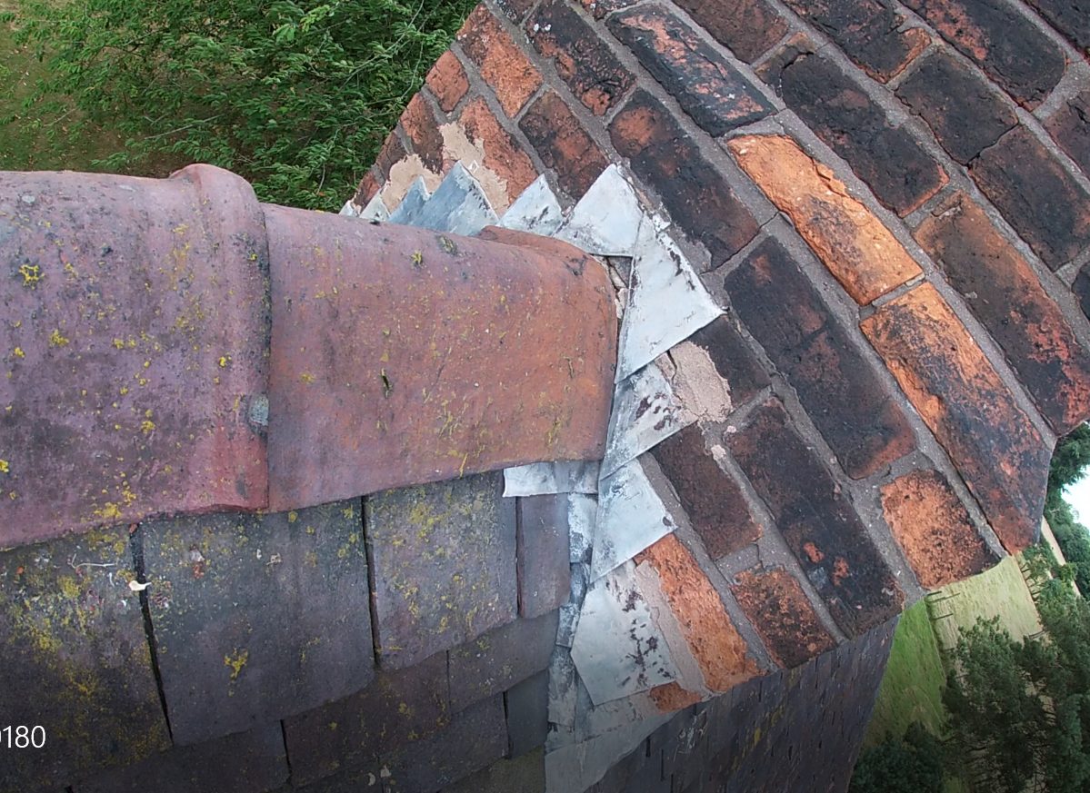
In figure 3 below, we have another example, which shows that there has been no attempt to form the correct saddle flashing and how this has left a moisture pathway for water ingress at this critical abutment detail. In fact, what we see is a continuation of the stepped lead flashings, which meet at the ridge tile apex and leaves an open joint for water ingress.
In older buildings we often see the complete absence of any lead flashings and see this abutment detail sealed with a mortar fillet, as in this case:

These cement fillets are often seen to have cracked and failed due to differential expansion/movement between dissimilar materials. with a common contributary factor being that the mortar mix/specification was incorrect. I would generally recommend that these cement fillets be replaced with code 4 lead flashings; though not always.
Correct Specification for Lead Saddle Flashings
Correct technical detailing can be found in Lead Sheet Training Academy guidance ‘Rolled Lead Sheet: The complete Manual.’ In figure 5 below you can clearly see how the saddle flashing should be installed before the ridge tile, along with the specification for lead overlaps. It’s interesting that the required welted edges are not seen in the pre-fabricated flashings seen in figure 1, but these welts can easily be dressed in retrospectively.

You’ll see in figure 5 that the head of the saddle flashing has been turned into the mortar bed joint as a finishing detail. I prefer to see the flashing left as a upstand, which is then protected by a lead cover (apron) flashing, but both finished versions are acceptable. Also note that in either case, the flashing should be turned into the mortar joint by a minimum 25mm.
Leave a Reply